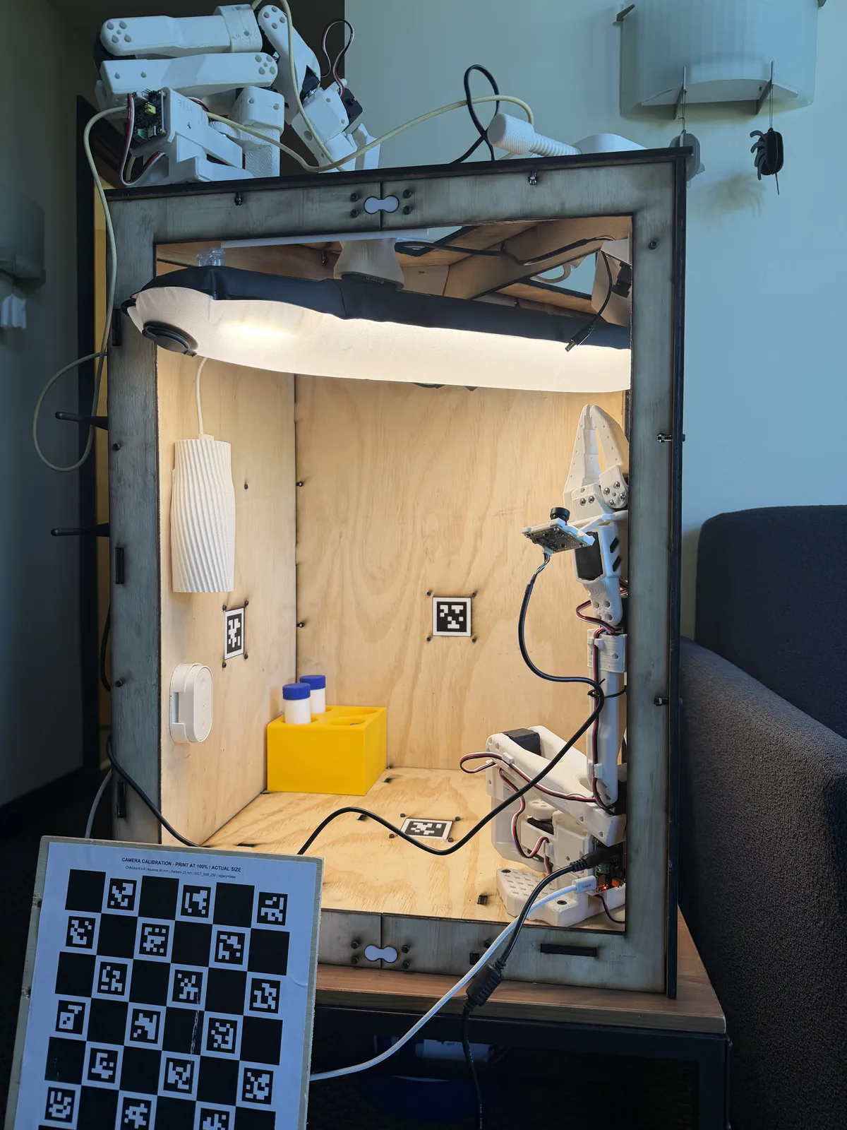
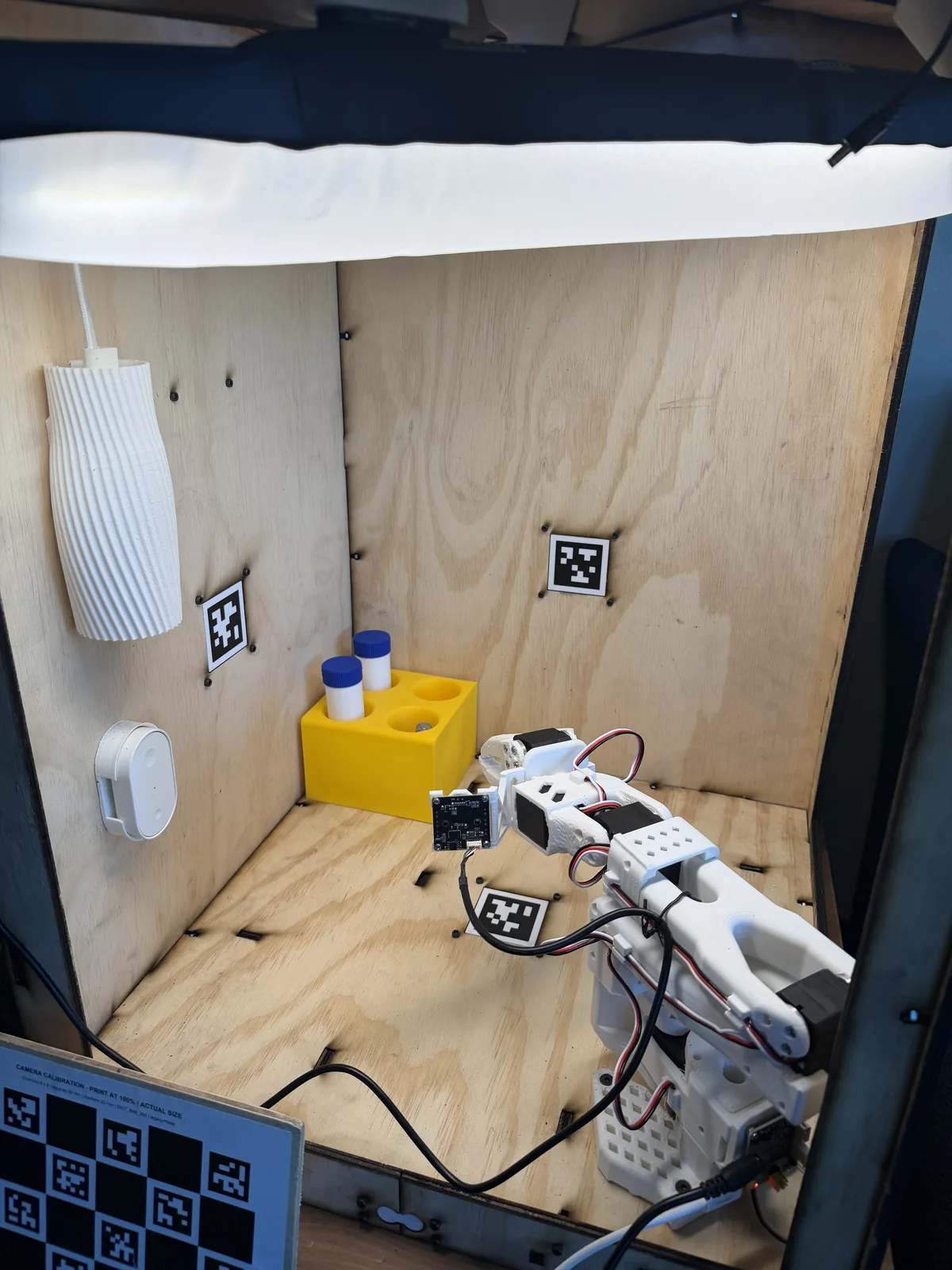
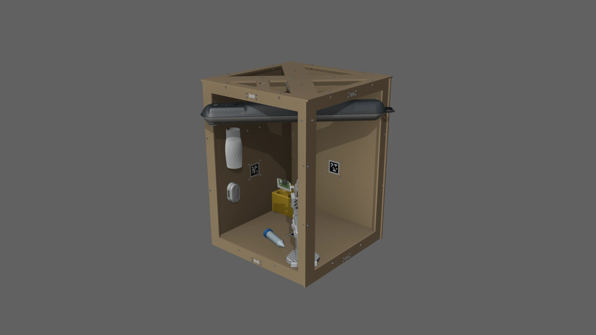
I built a portable workcell for the SO-101 arm so I can follow NVIDIA’s Sim-to-Real SO-101 tutorial from a college dorm. The frame comes out of four 2x2 ft sheets of 1/4 in plywood plus 3D-printed mounts. The robot, three cameras, the light, and the Jetson all mount at fixed positions, and the purchased parts come to about $154. I designed most of it with GPT-6 Astra working in Blender through Codex. That got me a working workcell, and it also got me a first revision I had to throw away. The design files are open source in so101-vla-portable-workcell.
What went wrong with my last setup
Last year, for my senior project, I collected teleoperation data and trained a policy for a bimanual task. That took about 360 validated episodes. The GR00T policy and its training dataset are still on Hugging Face. I also wanted to try sim-to-real transfer, but with only one semester, I ran out of time. I disassembled the stage, and sim-to-real has been in my backlog ever since. I did learn what better conditions for collecting data and deploying in the real world would look like.
The old stage had four problems:
- It was too large. It was hard to move and took up too much space.
- I couldn’t keep the camera position and angle consistent. The stage used a top camera and a wrist camera on each arm, and the top camera was a webcam with an adjustable neck, so once I disassembled and reassembled the stage, I could never get the same angle back.
- Nothing was measured or built to a spec, so building a matching simulation environment would have been hard. Even the camera height came from whatever the extension pole happened to be set to. I found it by trial and error until the whole stage fit in frame.
- I couldn’t find the webcam’s field of view or camera parameters online.
Why I started this one
When this semester started, I got an email about the Sears think[box] Embedded AI Microgrants at CWRU, which provide hardware such as the Jetson Orin Nano for student projects. I wanted the board, and I had an unfinished idea to use it for: VLA sim-to-real transfer with Isaac Sim, running on a Jetson Orin Nano and based on NVIDIA’s tutorial.
Part of why I picked this project is that I’m interested in fully autonomous labs, where AI models run experiments through physical robots. A setup like that needs a physical environment that stays the same between runs and a simulation that matches it. My last stage had neither.
Design requirements
Following the tutorial’s stage setup as written wasn’t going to work for me, so I set these requirements:
- Small enough for a dorm. The tutorial assumes a stable, spacious place where the stage can sit for a while. Most college students living in a dorm don’t have that unless they work in a research lab. The inner workspace is 425 × 425 × 570 mm.
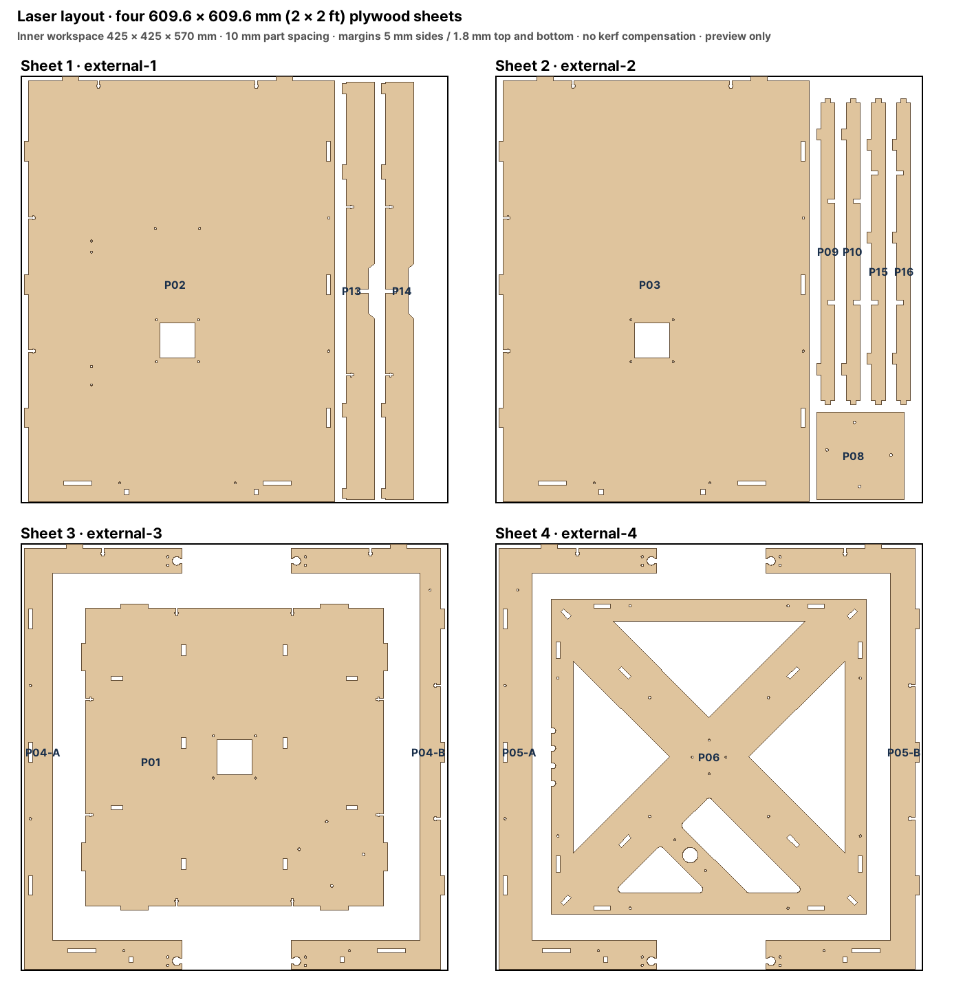
- Reassembles to the same state. The tutorial’s stage is flimsy, and when you reassemble it, the robot position and other conditions change. If I have to move, I need to take the workcell apart and still get the same environment back. The panels locate each other with tab-and-slot joints and are held together with M3 screws and captive nuts in T-slots. The robot bolts to the floor with four M4 screws, and every camera sits in a printed mount screwed to the frame.
- Fixed cameras. A webcam with an adjustable neck won’t point at the same spot twice. I also wanted to add a corner camera, so the workcell uses three Innomaker U20CAM-1080P board cameras: overhead, corner, and wrist. It’s the camera commonly used for the SO-101 wrist camera, so all three cameras are the same model, and I lock each lens after focusing.
- Cheap materials. I thought about acrylic panels, like the frame on older 3D printers such as the Anet A8, or aluminum extrusion. Both cost more than I needed to spend as a college student. I went with 1/4 in plywood because I have access to think[box]’s laser cutters and 2x2 ft panels are about $7 each.
- As few sheets as possible. I laid out all 15 panels to fit on four 2x2 ft sheets. A 2x4 ft sheet costs a bit more than two 2x2 sheets, is harder to carry, and bows more on the laser cutter bed.
- A second task. I’ve seen demos of GPT-6 Astra controlling a robot without task-specific training, like ROBOTIS’s AI Worker demo, so I wanted more than the tutorial’s tube-into-rack task. I added a lamp and a wall-mounted remote on the left side of the workcell so the robot can turn the light on and off.
- Parts anyone can get. I want anyone to be able to build the same workcell, so I stuck to 1/4 in (6 mm) plywood, 3D-printed parts, metric screws and nuts, and equipment sold internationally: the Innomaker cameras, a Ulanzi UA12 work light, and IKEA’s GRILLPLATS smart plug and remote, STRÅLA cord set, and SOLHETTA bulb.
- AprilTags as references. The floor, left wall, and back wall each have an AprilTag on a solid background. They give me fixed reference points for calibration. Later, I want to use them as anchors for AR glasses, so I can see the robot’s expected movement in 3D on top of the real workcell. I think that could help people understand what the robot is about to do.
Making sim-ready assets
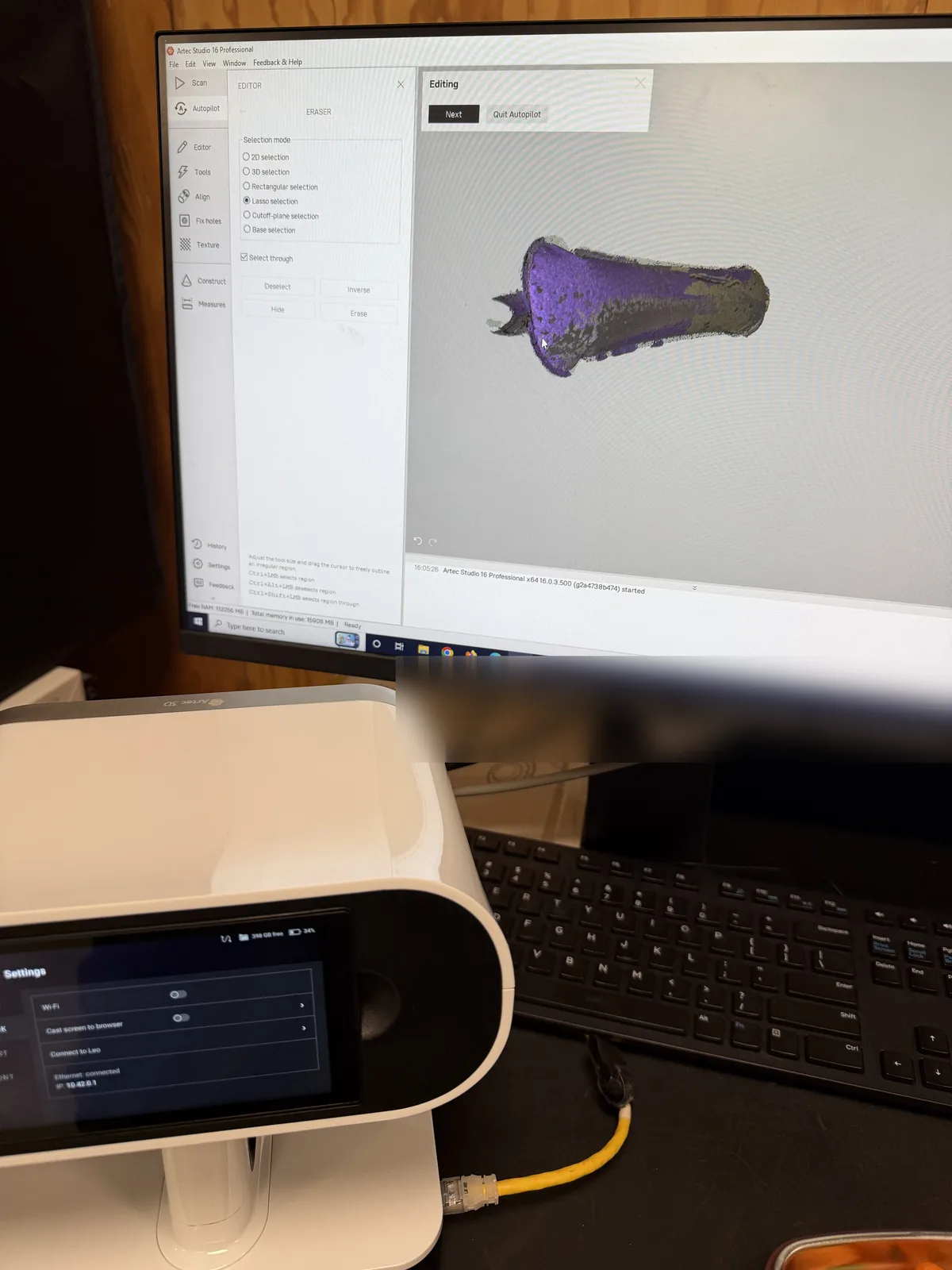
The Ulanzi UA12, the IKEA remote, and the IKEA bulb and socket have no 3D models online, so I scanned them with an Artec Leo structured-light scanner (the laser scanner was down) and converted the scans into assets. The scanner wasn’t very accurate, and the UA12’s tube shape made it worse.
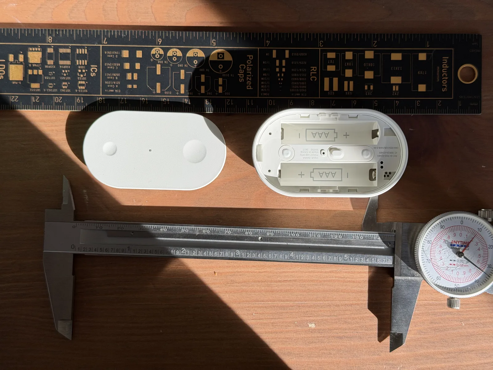
The bulb, the socket, and the remote were the hardest. For sim-to-real, and for Astra to design around real-world dimensions, I measured them with calipers and also used a flatbed scanner and multiple photos. The remote is the robot’s light switch, so it needs to be a sim-ready asset, and I also had to measure how far its button travels and how it deforms when pressed. I recorded a video of pressing the button, but I still had to measure the press depth with calipers. To test the switch in simulation, I connected Codex to my Ubuntu desktop with an RTX 5090 so it could control Isaac Sim directly.
I’m not entirely sure my assets count as sim-ready yet. NVIDIA has SimReady guidelines that I’ll look into if I need to.
Designing the workcell with an AI agent
I connected Codex to Blender so GPT-6 Astra could build and edit the models directly.
I tried to give Astra enough to work from: photos from multiple angles with rulers in the frame, the camera’s lens information, and videos, so it could extract accurate measurements from known reference dimensions and points. Even so, I still had to check its models by eye and tell it what was off, because Astra couldn’t fully design the parts accurately in 3D.
Astra can create a 3D stage and environment, but it has a limited understanding of how a physical stage works. I scrapped the first revision because the SO-101 couldn’t rest in its idle position. There wasn’t enough clearance, and I only noticed after I assembled it. Astra also didn’t fully understand how the panels slide and fit into each other so the workcell holds itself up, with the screws and nuts keeping the panels together.
The physical builds also caught fit problems that the digital checks missed. Laser-cut tolerances were larger than I expected, and the 3D-printed parts took several test prints to tune.
Iterating was slow. I sat for about an hour waiting on changes to my 3D-printed parts, trying to make them simpler, printable without supports, and use as little filament as possible.
I burned a lot of Codex tokens on this. I could only run this much 3D design experimentation because I was on the $200 ChatGPT Pro plan.
Other chores
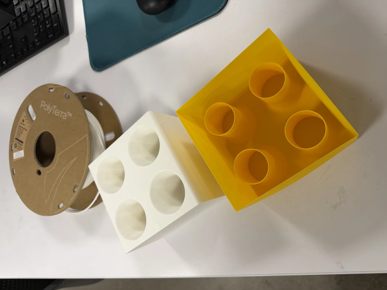
I had Codex split the tube rack into a yellow shell and a white inner structure. I already had white PLA, but yellow filament from think[box] costs $0.10 per gram, so printing the whole rack in yellow would have cost a lot. The shell has a 0.2 mm thin wall, so it took three or four tries to print it right.
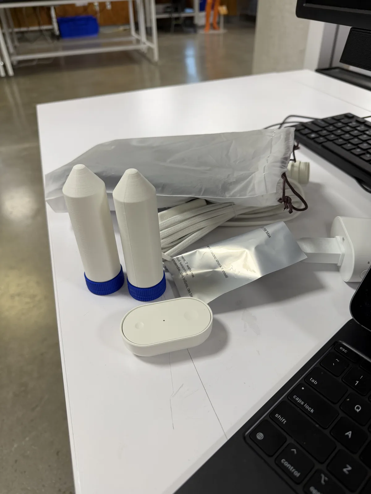
I also had Codex turn the tube’s sim-ready asset into printable STLs, with the tube and the screw cap as separate parts. Tubes on Amazon cost around $12 for a pack of at least 25, which is far more than I need. So I tested the tolerances and printed two tubes in the white PLA I already had and two caps in blue PLA from think[box]. The caps are small, so the think[box] filament cost very little.
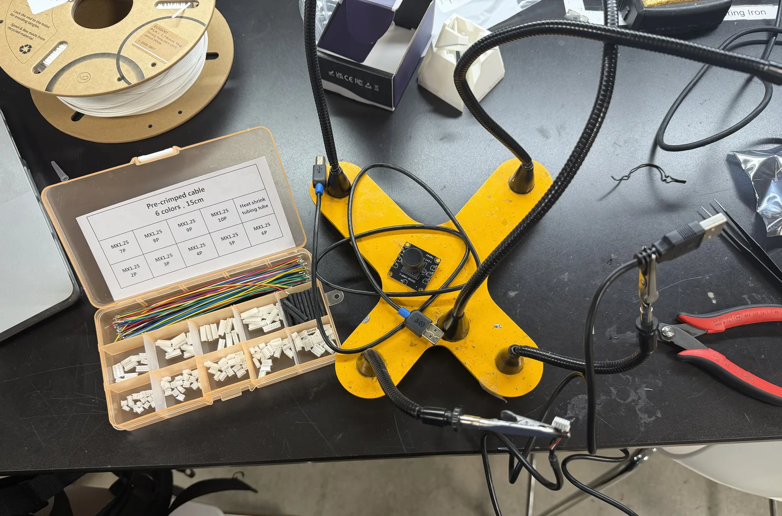
I also lost one camera’s connector cable. The Innomaker camera uses an MX1.25 (PicoBlade-style) connector, but that isn’t listed in the Innomaker 1080p camera documentation or anywhere else I could find, so I had to search a lot and compare photos to figure it out. I bought MX1.25 connector cables and two USB cables, cut a USB cable, looked up its wiring diagram, tested the connections, and soldered all four wires to make the same cable. It works fine. If you have an Innomaker camera and lose its cable, the MX1.25 PicoBlade connector is what you need. I hope this helps.
Where it stands
The workcell in the photos is the second revision. It’s built and in use, with a few 3D-printed parts that work around its remaining design errors. The published files are a third revision that removes those workarounds, which I haven’t fabricated yet. Three-camera capture and offline policy inference on the Jetson both work. I haven’t validated how repeatable reassembly is, or how closely the physical workcell matches the digital one.
Next steps
- Check the camera views on the physical workcell.
- Set up the workcell and teleoperation in Isaac Sim, collect demonstrations, and train a tube pick-and-place policy.
- Evaluate the policy on the physical workcell, then move on to the light-switch task.
- Collect real demonstrations and compare training on simulated data, real data, and a mix of both.
Loading comments…